For my fourth semester Audio Electronics class, we were tasked with building a sampler and sequencer using the Teensy 4.1 and Audio Shield.
Introduction
For this project, we are using the provided Teensy microcontroller and audio shield to build a sampler and sequencer, using buttons and potentiometers to control the sampling and sound effects.
The hardware setup is seemingly relatively simple, as the Teensy prepackaged breakouts have been set up for quick usage, allowing us to focus our time on the more time consuming programming and understanding behind the theoretical concepts. From sound effects such as pitch shift, echo, and filtering, we will be utilizing the Teensyduino library within an Arduino IDE.
Objective
Through this project, we’re aiming to gain a better understanding of digital signal processing (DSP) with a practical application. A very common and relatively simple use of DSP is in sound modification, which can be seen in products ranging from Auto-Tune to digital keyboards. Due to its simplicity, it’s a good first project when diving into the world of audio electronics and DSP. In this project, we will take short sound samples and apply a variety of sound effects to them, from bitcrusher to pitch shift.
Methods and Materials
We will be using the Teensy 4.1 microprocessor and Teensy audio shield as our primary source of hardware used for processing, supplemented by a plethora of buttons and potentiometers for user input, and wires to connect parts of the circuit together. As for software, we will be using the Teensyduino library accompanied by the traditional Arduino IDE. (Note that the Windows app version is not compatible with Teensyduino.) The last piece of software we needed to download was the Teensy Loader. Pretty easy to set up overall! Of course, things will prove to move in a totally different direction once we actually try to compile and run our code.
Procedures
Planning
As people with less experience in the world of DSP, Andy and I went on the search for previous projects that were similar to our end goal. We were able to find a project that had developed a sampler based on an earlier Teensy version. It was well documented and clear, so we chose to follow along with their project, since it was complete with a hardware and software setup. Since we were both remaining virtual for the rest of the year, we chose to build everything independently, although we worked together to troubleshoot issues.
Hardware
This project involves both a hardware and a software component. Due to the nature of the virtual environment, the class as a whole opted for a less involved approach, and we selected Teensy microcontrollers to replace a section of our hardware.
After receiving the Teensy 4.1 and Audio Shield, we had to solder female pin headers so we could attach the two pieces, which weren’t originally designed to be used together. Otherwise, the Teensy was physically ready to go! The biggest hassle involving Teensy setup is the code behind it to link pieces together.
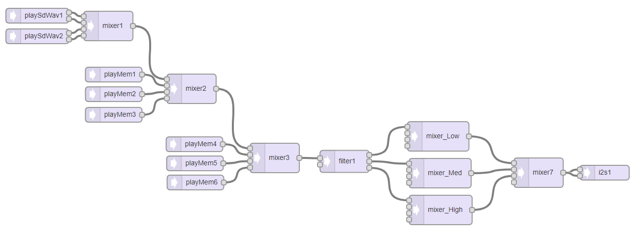 flow chart using Audio System Design Tool
Using the Audio System Design Tool, we’re able to design the connections between our circuit, and on export, we’re able to get setup code generated for us, shown below.
#include <Audio.h>
#include <Wire.h>
#include <SPI.h>
#include <SD.h>
#include <SerialFlash.h>
AudioPlaySdWav playSdWav1;
AudioPlaySdWav playSdWav2;
AudioMixer4 mixer1;
AudioPlayMemory playMem1;
AudioPlayMemory playMem2;
AudioPlayMemory playMem3;
AudioMixer4 mixer2;
AudioPlayMemory playMem4;
AudioPlayMemory playMem5;
AudioPlayMemory playMem6;
AudioMixer4 mixer3;
AudioFilterStateVariable filter1;
AudioMixer4 mixer_Low;
AudioMixer4 mixer_Med;
AudioMixer4 mixer_High;
AudioMixer4 mixer7;
AudioOutputI2S i2s1;
AudioConnection patchCord1(playSdWav1, 0, mixer1, 0);
AudioConnection patchCord2(playSdWav1, 1, mixer1, 1);
AudioConnection patchCord3(playSdWav2, 0, mixer1, 2);
AudioConnection patchCord4(playSdWav2, 1, mixer1, 3);
AudioConnection patchCord5(mixer1, 0, mixer2, 0);
AudioConnection patchCord6(playMem1, 0, mixer2, 1);
AudioConnection patchCord7(playMem2, 0, mixer2, 2);
AudioConnection patchCord8(playMem3, 0, mixer2, 3);
AudioConnection patchCord9(mixer2, 0, mixer3, 0);
AudioConnection patchCord10(playMem4, 0, mixer3, 1);
AudioConnection patchCord11(playMem5, 0, mixer3, 2);
AudioConnection patchCord12(playMem6, 0, mixer3, 3);
AudioConnection patchCord13(mixer3, 0, filter1, 0);
AudioConnection patchCord14(filter1, 0, mixer_Low, 0);
AudioConnection patchCord15(filter1, 1, mixer_Med, 0);
AudioConnection patchCord16(filter1, 2, mixer_High, 0);
AudioConnection patchCord17(mixer_Low, 0, mixer7, 0);
AudioConnection patchCord18(mixer_Med, 0, mixer7, 1);
AudioConnection patchCord19(mixer_High, 0, mixer7, 2);
AudioConnection patchCord20(mixer7, 0, i2s1, 0);
AudioConnection patchCord21(mixer7, 0, i2s1, 1);
In terms of hardware used for product interaction, this was a super simple circuit. With 8 pushbuttons and 3 potentiometers, we were able to assemble it with the help of a very bare schematic.
Software Development
With software, there were two things that needed to be accomplished: the former being the setup of audio files, and the latter being the code to run the Teensy itself. However, I first set up a folder on my computer called audio, where I stored two folders: one for my actual code and audio files, and the other for audio file conversation. I’ll speak more on that later.
Directory List: note that I am (update: as of June 2022, I am no longer) a Windows user (for the GUIs) but I also use Ubuntu 20.04 on Windows Subsystem for Linux (for the terminal). Since I’m using Arduino on Windows, most of my stuff is going to be on the Windows end, but if it involves the terminal, it’ll probably be in Linux. Thankfully I don’t think I use the terminal a whole lot in this project!
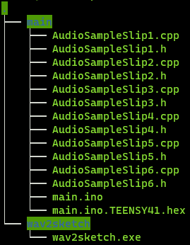 view of my directory
For the code to run the audio file, it had to be in binary form, so using the wav2sketch executable file, I converted 6 short 2 second WAV files, named Slip1.wav, Slip2.wav, Slip3.wav, etc., into C++ in the wav2sketch folder by clicking on the executable file. The program’s a bit janky, since it converted files in some cases but not in others. Sometimes I had to remove Slip1.wav and the associated C++ files to get it to convert the others!
As it turns out, the project we were following shared their code, too! (Yay, open source!) After moving the C++ versions of the WAV files into the folder with my main Teensy code in main.ino, everything compiled, and after exporting, in main there is a main.ino.TEENSY41.hex file. Unfortunately, this is where my success ended and things started getting dicey.
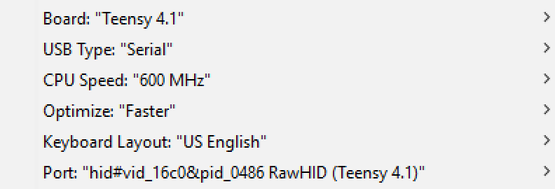
Teensy itself is not a serial device — it uses HID. It has to be programmed once using the preloaded Blink program in order for it to show up in the port section of board setup. For most people, their port is COM3 or COM4, but for mine, it had a really janky name. Google said it was fine, but I’m not really sure if it actually is.
Tools Menu on my Arduino IDE with Board setup below.
 tools menu
After compiling, the Arduino IDE tells us that it was successful. If it wasn’t, it would display an error message at the bottom saying where things went wrong.
 IDE display
We would then be redirected to the Teensy Loader application, which indicated that we should press the button on the Teensy located between the continuously flashing LED and SD card slot.
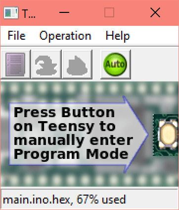 Teensy Loader
After pressing the button, Windows would make the USB sound. According to Make Tech Easier, this can be a sign that there’s a problem. Quite frankly, there was. No matter what I did, the Teensy would not enter the HalfKay Bootloader Mode for me to upload and run my code. Even after extensive troubleshooting, it’s not clear why. After uploading either of the test files blink_fast.hex or blink_slow.hex, it was unwilling to program. I tried uploading a blank sketch, and the Teensy Loader still indicated that something was taking up space.
With the semester soon approaching a close, we made the difficult decision to halt the project since we weren’t getting anywhere.
Results
Circuit Shots
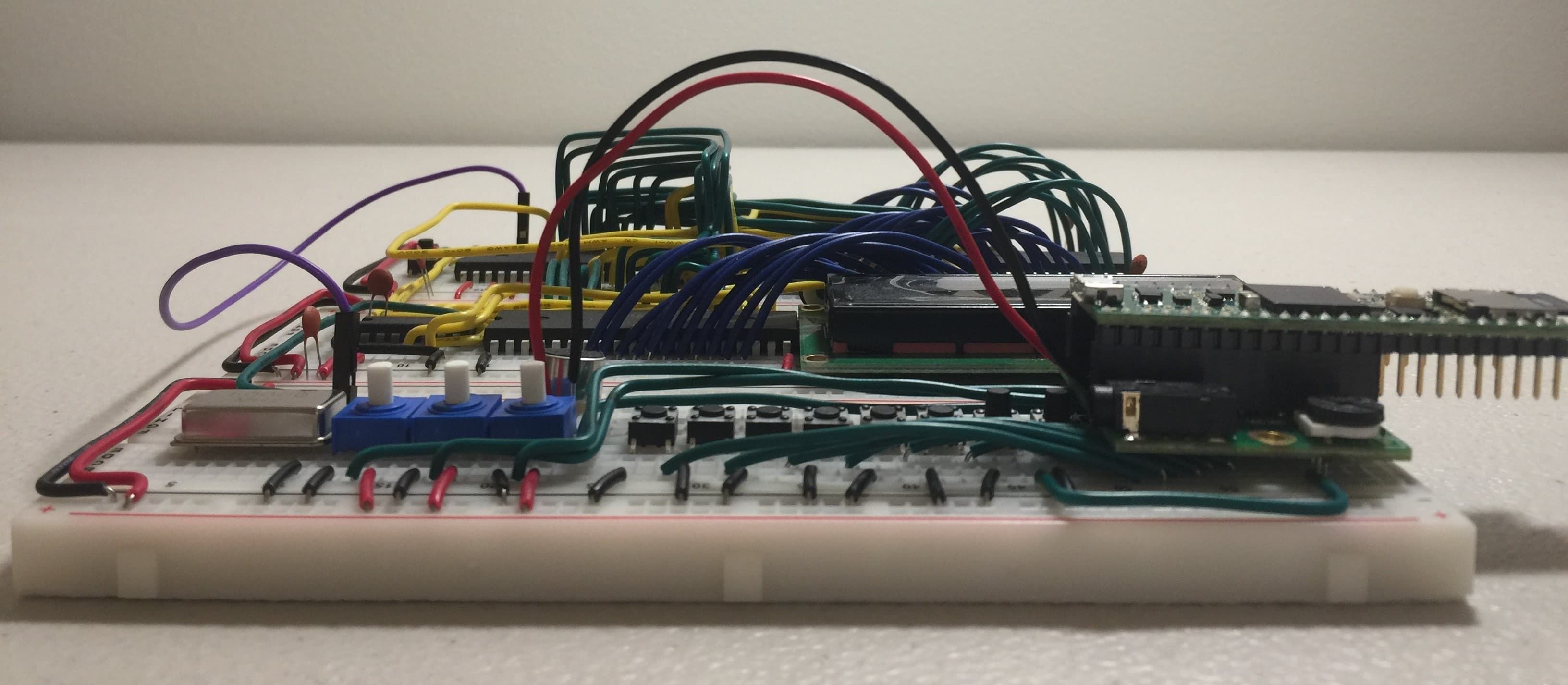 side view of circuit
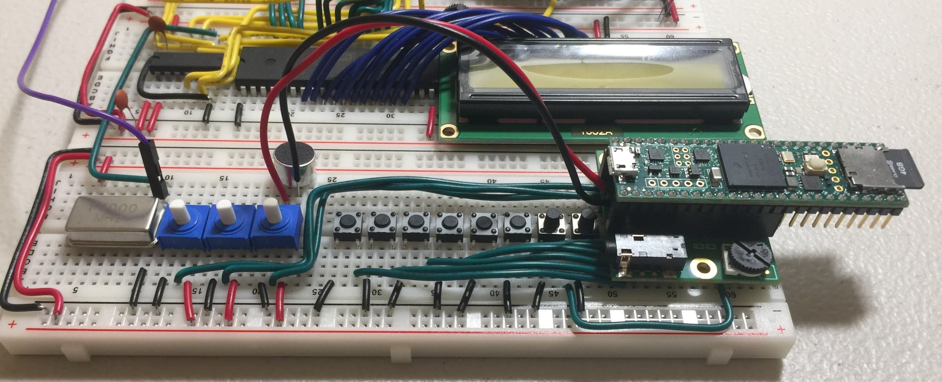 slant view of circuit
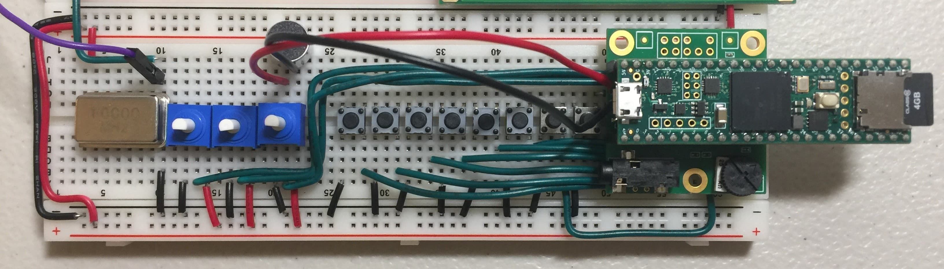 top view of circuit
In all seriousness, I’m thankful I wired the circuit before I started on the software development, since the discrete component part of the project was super successful. (I finished it in a single block!) If possible, in the summer, I’d like to see if the Teensy was the problem, which seems likely, and try to get it working as planned.
Analysis
As we know from Analog, signals are waves that can be represented by sine and cosine functions, and using different techniques, we can manipulate the signal to alter its sound quality — from cleaning up the sound to changing its timbre, we’ve got a variety of choices!
One such way of doing this is through digital signal processing (DSP). When a signal is digitized, it can easily be manipulated through the 0s and 1s that are representing it. Instead of using purely hardware, we’re able to more easily transfer our thoughts from our heads to actual results through code in embedded systems.
However, since our input and output will be an analog signal, we have to produce a shift between analog and digital (and vice versa). The entire processes is illustrated well by the diagram below from Chapter 3 of The Scientist and Engineer’s Guide to Digital Signal Processing:
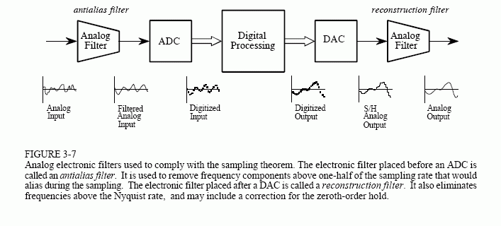 explanation of DSP from analog input to analog output
Our input signal first has to be filtered to remove noise to produce the best results during conversion. It then undergoes conversion through an analog to digital convertor (ADC). An ADC takes the analog input and for a given time interval, approximates the value of the signal and represents it using binary, like the image below from All About Circuits.
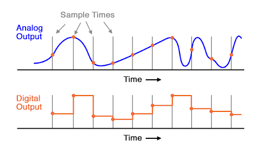 conversion from analog to digital waveform
The shorter the sampling interval, the smoother it looks. The more bits the output has, the greater resolution it has, which also results in a smoother curve. The number of bits corresponds to the number of states it can output to — for example, a 4-bit ADC will have 24 states. ADC looks a little bit like reverse integration, to be honest! Of course, a lot of this is rooted in math.
A digital to analog convertor (DAC) basically undos what an ADC does. Analog Planet gives a great summary of both ADC and DAC.
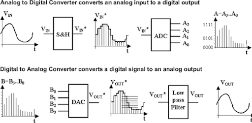 comparison between what ADC and DAC do
Audio file formats (i.e., WAV and mp3) are digital formats to the analog audio we physically hear, we rely on these technologies in order to do any sort of audio manipulation! Although ADC and DAC are not that complicated, since signals in real life are typically analog.
Bringing us back to DSP, it’s critical in the handling of analog signals because it allows for faster transmission and easier storage, such as saving a recording to a computer or phone. Noise cancellation is also achieved using DSP (destructive interference to cancel out sound). A gross simplification of DSP would be taking data from a signal and performing mathematical operations on it to achieve an end goal you may have. There’s still a lot more in this field left to learn!
Conclusion and Reflections
Theoretically, if everything had worked, we should have been able to record our own audio clips to edit using the Teensy 4.1 and Audio Shield, as detailed above in the Analysis section. The lengths of the audio clips would’ve been limited by the Teensy, but the theory behind a more sophisticated sampler and sequencer would’ve been the same.
In the future, we could continue building on using discrete components (a much more daunting and time consuming task than it may seem) so we can control some aspects of the circuit, such as the input and processing quality. Of course, we’re always constrained by time, money, and other resources.
Research is a vital skill to have, because it helps you learn things and build from them, as well as letting you find and utilize the best resources at your disposal. It doesn’t have to be academic research — for example, you could be researching which domain name is best for a project you have in mind! Although the Audio project was likely still quite different from senior research, we still had to find information to build our projects off of. It’s certainly good practice for next year!
If there’s any skill I learned through this project, it’s been how to troubleshoot quickly. Since we were met with so many problems throughout the project, it was critical that we resolve as many of them as soon as possible. In fact, we were able to resolve the first issues we encountered (i.e., duplicate libraries, non compiling code, etc.). Sadly, we were still heavily constrained by time, so we weren’t able to fix the Teensy. Of course, I also learned a lot of technical stuff like how DSP works, but I think that was my biggest takeaway.
Overall, I really enjoyed putting the circuit together. I know that it’s not a super complicated circuit — it’s literally just wires, pushbuttons, and potentiometers, but I really missed the feeling of touching discrete components. This is the part of electronics that makes me like it just as much, if not more, than CS. Every time I think that electronics isn’t for me, as soon as I build something again, the spark comes back.
I’m disappointed that the Teensy didn’t work for me, since I’m really someone that is highly motivated by tangible final products. It’s much more difficult to try to experiment with different functions through imagination and theory rather than physically altering code and hearing the effects. I guess there’s not a whole lot that I could’ve done otherwise, but I would’ve liked a better understanding of the theory going in before starting the project. Since 4th Quarter goes by so fast, it’s hard to catch up on the theory since you just don’t have enough time.
To future Audio students: there’s a lot of stuff that’s probably confusing in Audio (so much math!! AAAAAAAAAAAAA), but it’s still lots of fun. Don’t be afraid to ask your friends for help and collaborate on your projects. Most of all, have fun!!
References
You can take a look below at where I got my research, inspiration, and more! Special thanks to Kari (literally class carry! that was a terrible pun) for coming up with this project, explaining it eloquently, and helping us troubleshoot.